
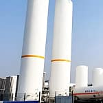
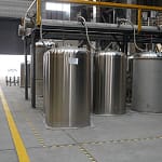

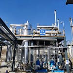


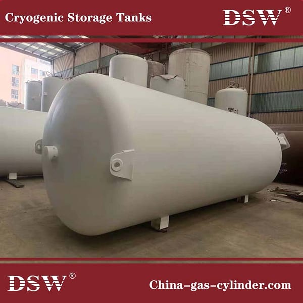

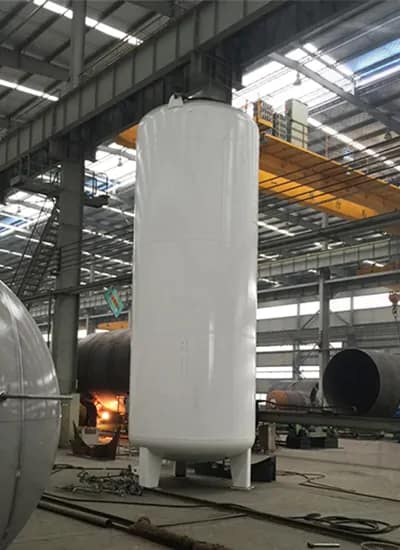
A cryogenic CO2 tank is a precision-engineered pressure vessel designed to safely store CO₂ at low temperatures (-20°C to -35°C) and high pressures (up to 22 bar / 320 psig). Our factory produces high-quality liquid CO2 tanks using certified materials, advanced engineering practices, and strict quality control. Each CO2 cryogenic tank is built for durability, safety, and long-term industrial use.
This article details the step-by-step process for manufacturing liquid CO2 storage tanks and offers insights for industrial engineers and buyers.
What Is a Cryogenic CO₂ Storage Tank?
A cryogenic CO₂ storage tank is a double-wall insulated vessel that maintains CO₂ in liquid form at low temperature and high pressure. These tanks prevent vaporization and ensure safe handling for industrial, food, and chemical applications.
Key applications include:
- Industrial gas supply (welding, cutting, chemical processes)
- Beverage carbonation and food preservation
- Fire suppression and refrigeration systems
- Scientific and research applications requiring high-purity CO₂
Design Standards for Liquid CO2 Tanks
Cryogenic CO2 tanks must meet international pressure vessel standards:
- ASME Section VIII, Division 1 – Pressure vessel code for industrial tanks
- PED / EN 13445 – European pressure equipment directive for safe operation
Compliance ensures each liquid CO2 tank is structurally sound, safe, and reliable for long-term cryogenic storage.
Materials Used in Cryogenic CO₂ Tanks
Material selection is critical to withstand low temperatures, high pressure, and CO₂’s corrosive nature.
| Component | Material | Purpose |
|---|---|---|
| Inner Vessel | SA-516 Gr. 70 Carbon Steel | High toughness at low temperature |
| Optional Inner | SA-240 Stainless Steel | Enhanced corrosion resistance |
| Outer Jacket | SA-285 / SA-537 Steel | Structural strength and insulation support |
Step-by-Step Process for Manufacturing a Liquid CO2 Tank
2. Engineering Design
The design follows ASME Section VIII, Division 1 or PED/EN 13445 standards.
The wall thickness of the cylindrical shell is calculated as:
t = (P × R) / (S × E − 0.6P)Where:
- t = minimum wall thickness (mm)
- P = design pressure (MPa)
- R = inner radius of shell (mm)
- S = allowable stress of material (MPa)
- E = weld efficiency (typically 0.85–1.0)
Example: For a 20 bar design pressure and 1500 mm radius using SA-516 Gr. 70 steel with S = 138 MPa and E = 0.9, the required thickness ≈ 32 mm.
Design Pressure & Temperature:
Design pressure: 22 bar (normal working) / 24–26 bar (test)
Design temperature: –40 °C to +50 °C
Capacity Range: From 5 m³ to 100 m³, depending on industrial use.
| Product Parameter | Details |
|---|---|
| Name | 10m³ 16bar Cryogenic LCO₂ Gas Storage Tank |
| Price | [Insert Price] |
| Loading Medium | LCO₂ |
| Effective Volume | 10.0 m³ |
| Working Pressure | 1.6 MPa |
| Overall Dimension | Ø2000 × 7895 mm |
| Design Temperature | -196 ℃ ~ 60 ℃ |
| Outer Cylinder Material | Q345-R |
| Inner Cylinder Material | S30408 |
| Insulation | Vacuum Powder Insulation |
Step 2: Cutting and Forming
- Plates are CNC plasma cut for precision.
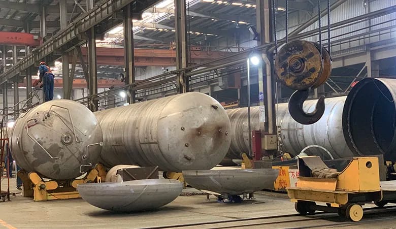
- Rolling machines shape plates into cylindrical shells.
- Dished ends are hot-pressed per DIN 28011 or ASME F&D head geometry.
Step 3: Welding and Assembly
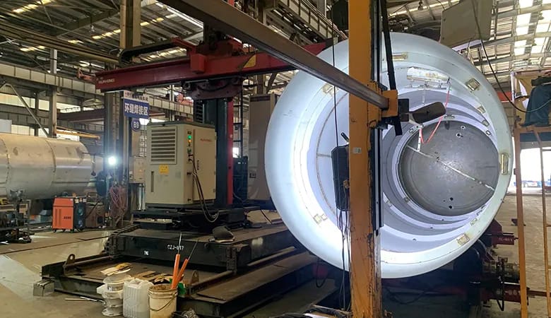
- Submerged Arc Welding (SAW) for main seams
- GTAW/TIG welding for nozzles and fittings
- Non-destructive testing (NDT): Radiography (RT), Ultrasonic (UT), Dye Penetrant (PT)
Step 4: Insulation for Liquid CO₂ Tanks
- Double-wall construction with high vacuum (<5×10⁻³ mbar)
- Expanded perlite + multi-layer aluminized mylar (MLI)
- Static evaporation rate (NER): 0.2–0.3% per day
Step 5: Surface Treatment
- Inner vessel: sandblasted and coated for cryogenic compatibility
- Outer shell: epoxy paint ≥250 μm or polished stainless steel finish
Step 6: Instrumentation and Safety Devices
- Safety relief valves
- Pressure gauges
- Level gauges
- Fill/withdrawal valves
Step 7: Hydrostatic and Pneumatic Testing
- Hydrostatic test at 1.5× design pressure
- Pneumatic leak test with helium or nitrogen
- Vacuum retention testing
Step 8: Final Inspection and Certification
- Dimensional inspection (±2 mm)
- NDT reports for weld integrity
- Hydrostatic test certificates
- ASME “U” stamp or CE mark
7. Instrumentation and Safety Devices
- Safety relief valves
- Level gauges
- Pressure gauges
- Fill/withdrawal valves
Step 9: Packaging and Delivery
- Lifting lugs, saddles, and skid mounts for secure transport
- Export packaging follows ISO 1161 container handling standards
How to Choose a Reliable Liquid CO₂ Tank Manufacturer
- ASME or PED-certified facility
- Proven NDT and quality control
- Material traceability
- International delivery capability
At our factory, each CO₂ tank is built for safety, efficiency, and long service life, providing a reliable solution for industrial storage and supply.
TECHNICAL QUESTIONS
Frequently asked questions About Cryogenic CO2 Tanks
Liquid CO₂ tanks are typically designed for a working pressure of 20–22 bar (2.0–2.2 MPa) with a maximum test pressure of 1.5× design pressure. This ensures the vessel can safely accommodate pressure fluctuations and maintain cryogenic CO₂ in liquid form without risk of structural failure.
The inner vessel typically uses SA-516 Gr. 70 carbon steel for its toughness at low temperatures, or optionally SA-240 stainless steel for enhanced corrosion resistance. Outer jackets and insulation shells use SA-285 or SA-537 steel for structural strength. All materials conform to ASME Section II requirements to meet cryogenic and pressure vessel standards.
With proper maintenance, insulation monitoring, and periodic NDT inspections (ultrasonic testing, radiography), liquid CO₂ tanks can reliably operate for 15–20 years. Factors affecting service life include cyclic loading, insulation degradation, and corrosion exposure.
The static evaporation rate (NER) for a double-wall vacuum-insulated CO₂ tank is typically 0.2–0.3% per day. This depends on insulation type (vacuum, perlite, multilayer insulation), tank size, ambient temperature, and operational load.
The minimum wall thickness (t) is calculated using the ASME Section VIII formula: t = (P × R) / (S × E − 0.6P), where P is design pressure, R is inner radius, S is allowable material stress, and E is weld efficiency. This ensures the vessel can withstand internal pressure at cryogenic temperatures without structural failure.
Conclusion
The production of a liquid-CO₂ tank is a highly technical process involving precise material selection, adherence to pressure vessel design codes, advanced insulation technology, and rigorous testing. At our factory, each tank is engineered for safety, efficiency, and long service life, providing customers with a reliable solution for CO₂ storage and supply.


No comment